I. First, clarify: What problems does your production line need to solve?
Before listing the equipment, you must first answer a fundamental question: What kind of boards will this production line produce, and how?
Different business models have drastically different requirements for production line configuration:
High-volume single-product production (e.g., mobile phone motherboards, tablet computers): Prioritizing maximum speed, configurations often favor high-speed machines and multiple parallel lines.
Multiple-product, low-volume production with frequent line changes (e.g., industrial control boards, automotive electronics, sample prototyping): Speed is not the primary priority; changeover efficiency and equipment flexibility are key. In this scenario, the key selection factor for pick-and-place machines is not "fastest," but rather "most comprehensive functionality"—compatible with packages ranging from 0603 to large ICs, capable of mounting irregularly shaped components, and equipped with an intelligent vision recognition system.
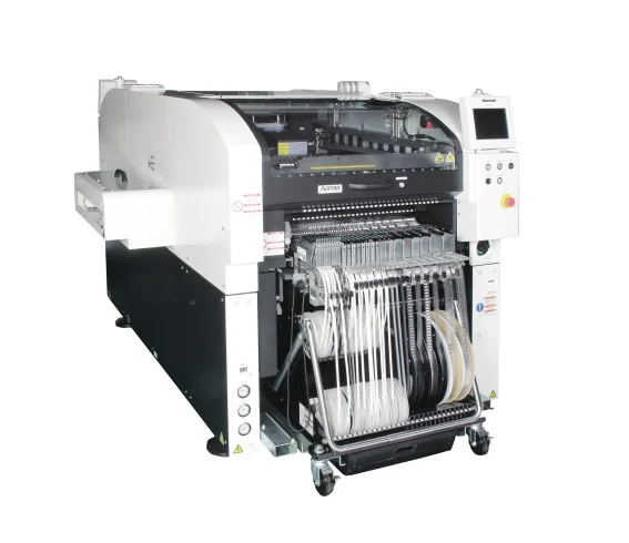
The Panasonic NPM series is commonly found in complete production line solutions precisely because it achieves a good balance between speed and versatility. However, the specific number of machines required needs to be determined based on actual production capacity targets, rather than blindly piling on equipment.
II. Complete Production Line Equipment Matrix: Standard Flow from Board Input to Board Output
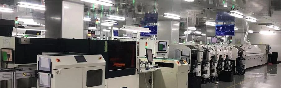
A standard SMT complete production line follows this process sequence: Board Loader → Printer → SPI (Solder Paste Inspection) → Pick-and-Place Machine → Reflow Soldering → AOI (Automated Optical Inspection) → Board Unloading Machine. This sequence is crucial because each process depends on the result of the previous one.
Specific configuration points for each station's equipment:
1. Automatic Board Loading and Unloading Machine: Responsible for the input and output of PCB boards. If the production line has frequent changeovers and a tight schedule, it is recommended to equip a pair of automatic board loading and unloading machines to reduce manual intervention.
2. Fully Automated Solder Paste Printer: The quality of solder paste printing directly affects the yield of subsequent placement and soldering. Multi-variety production means frequent changes to stencils and programs; the program memory and automatic stencil cleaning functions of a fully automated printer are very useful in this situation. When selecting a printer, focus on printing accuracy (recommended within ±15μm) and the stability of the alignment system. Common brands in the industry include DEK, ASKS, and GKG.
3. SPI (Solder Paste Inspection System): Located after the printer and before the pick-and-place machine, it is used to detect the volume, height, and offset of the solder paste. A 3D SPI is recommended to ensure the detection accuracy meets the requirements of high-density boards. The significance of this station is to detect printing defects early and prevent solder paste problems from flowing into the placement process and causing batch rework.
4. Pick-and-Place Machine – The Core of the Production Line: This is the "heart" of the entire production line and also the part with the largest investment. For the NPM series, there are two common configuration approaches:
High-speed machine + general-purpose machine combination: One high-speed machine handles a large number of resistors and capacitors, while a general-purpose machine specializes in handling irregularly shaped components such as ICs and connectors. This combination is highly efficient, but requires more personnel to coordinate during program switching.
Single model uniform configuration: If the product types are relatively concentrated, all machines can be of the same model, simplifying spare parts management and personnel training.
The performance specifications of pick-and-place machines need to be viewed rationally. The CPH (placement points per hour) marked on the nameplate is an ideal laboratory value. The actual UPH (upper capacity per hour) in the production line is usually only 40%~60% of the nominal value because the time for feeder indexing, reference point identification, and nozzle replacement must also be taken into account. When configuring capacity, it is essential to calculate based on the actual efficiency after discounting.
5. Reflow Oven Responsible for melting solder paste and forming solder joints. Flexible production lines require reflow ovens to be "stable and easily adjustable." Generally, 6~8 temperature zones are sufficient to meet the requirements of lead-free processes. The key is stable temperature rise and precise temperature control in the cooling zone. If the product is sensitive to soldering oxidation, consider models equipped with nitrogen protection.
6. AOI (Automated Optical Inspection) Located after reflow soldering, it's used to inspect for surface defects in placement and soldering. Whether to configure AOI depends on the customer's quality requirements—if working with large clients and dealing with a wide variety of products, AOI is almost standard; if the product defect tolerance is high, manual visual inspection can be used, but efficiency and coverage will be significantly reduced.
III. Easily Overlooked "Software Configurations"
Beyond hardware, the smooth operation of the entire production line often depends on several easily overlooked details:
Feeder Reserves Insufficient feeder quantity requires frequent disassembly and reassembly during line changes, severely slowing down efficiency. Industry experience recommends that each model be equipped with at least twice the maximum feeder capacity of the equipment. For example, if a pick-and-place machine can hold a maximum of 80 feeders, equip it with 160 to avoid feeder bottlenecks during line changes.
Software and System Integration Multi-variety production means frequent program switching is required. When selecting equipment, prioritize solutions that can automatically recognize imported BOMs, have fast parameter memorization, and integrate with ERP/MES systems. Furthermore, the compatibility of communication protocols among all equipment on the production line needs to be confirmed in advance to avoid data inconsistencies later.
Line Layout: In a standard layout, it is recommended to leave 0.8-1.2 meters of operating clearance between devices to facilitate personnel access, maintenance, and feeder trolley movement. Buffers can also be set up between processes to decouple the rhythm differences between preceding and following processes—this way, a brief shutdown of one device will not immediately block the entire production line.
IV. Typical Configuration Schemes for Reference
The following are two different complete line configuration ideas for reference:
Scheme 1: High-volume production (large batch, few line changes)
- Board loading machine + fully automatic printer + SPI
- 2~3 high-speed pick-and-place machines (parallel operation)
- Reflow oven + AOI + X-Ray (BGA inspection)
- Budget reference: Total investment for the entire line is approximately 4-5 million RMB.
Scheme 2: Flexible multi-variety (small batch, high line changeover frequency)
- Board loading machine + fully automatic printer (with automatic screen cleaning function)
- 1 medium-speed high-precision pick-and-place machine (compatible with irregularly shaped components) + 1 general-purpose machine
- Reflow oven + AOI
- Key focus: Sufficient feeders, easy-to-operate software, and line changeover time controlled within 15 minutes.
Summary
Configuring an SMT complete line is essentially about finding a balance between capacity, cost, and flexibility. Hardware procurement is only the first step. The "soft skills"—feeder matching, software integration, and line layout—are the watershed that determines whether a production line can operate efficiently. Spending more time on requirements analysis and on-site verification during the equipment selection phase is far better than making compromises and modifications after the equipment has been delivered.